We support those that like to do the job themselves. If you find these instructions useful, please help support us by purchasing the parts you need from us. These units are supposed to be a secret, so we are spilling the beans as we would like to help everyone. Also note that nice instructions like this are included with a lot of the DIY parts we sell. We want to help and work with those which want to install and rebuild their own units. Please feel free to contact us with any of your GT-R needs.
The first step is the remove the ETS unit from the trans. Instructions on how to do that is HERE.
Set the unit up on a vise as shown in the picture below. Note, you want the vise to hold it at the bolt heads and not the body of the housing. The housing can be easily damaged if pressure is applied, so don't put pressure on the housing, only the bolts.
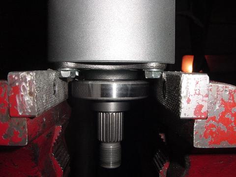
After it is secure on the vise, you can then get started.
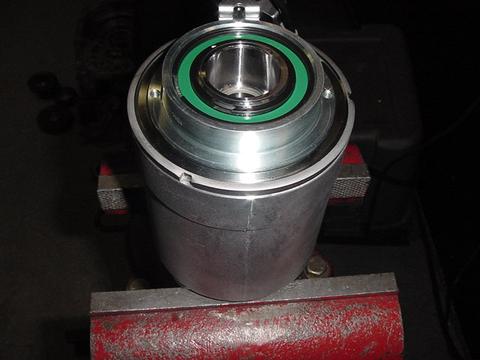
Remove the coil c-clip:
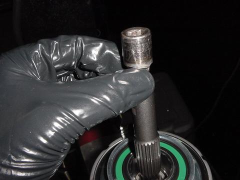
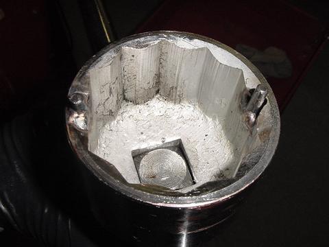
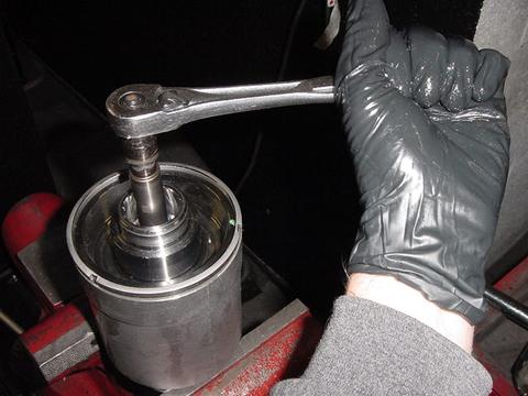
I had a broken ETS output shaft which I modified to use as a clutch pressure and friction tester. All I did was weld a socket to the end of the shaft as you see in the picture below. This allows me to put a torque wrench on the shaft and measure what kind of resistance I am seeing via the clutches. This ETS unit came out of a 2013 trans with 2k miles on it, so I got 10NM of resistance when I tried to turn the assembly. This is an indication to me that this unit is likely to be in great shape.
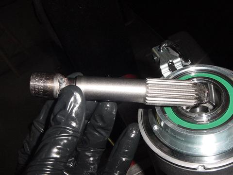
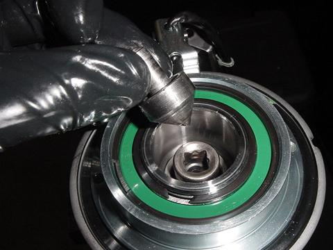
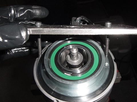
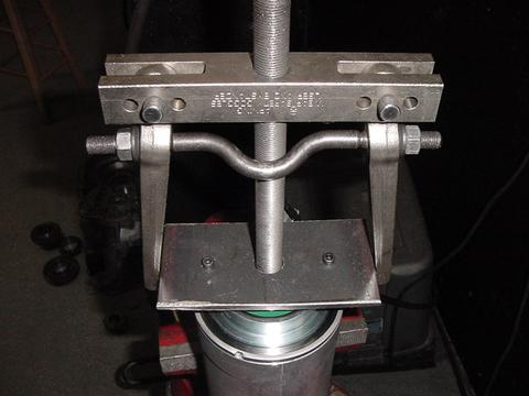
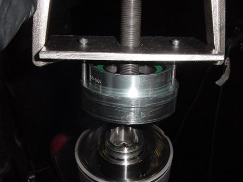
This tool has 2 purposes. It can be used to check torque values, but is also used as a pressure point for removing the coil via a puller. What we do is install the shaft into the assembly and let it drop to the bottom. I then take the puller and install it as you see in the picture below. Note I also made a special plate so I can pull the coil off:
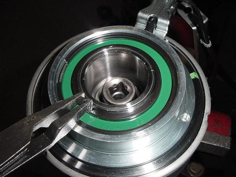
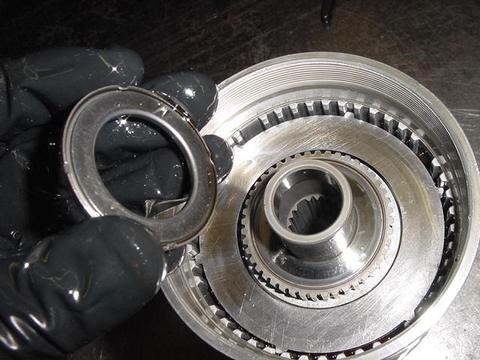
Remove the retaining ring for the cap. I have a special tool for this, but am showing the way it can be done without it and only using a chisel and hammer. Tap it counterclockwise until it loosens and comes off. Set it aside.

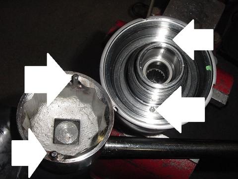
Making a simple tool for the removal of the cap makes life a lot easier. What I did was take a cheap large socket and weld pins to it that fit the holes in the plate. Picture below:
Now you can very easily turn the cap:
Special note: turn the cap clockwise all of the way until it stops. If the unit is healthy, it will turn 90 degrees and then stop. If it turns more than 90, then you have friction wear and the friction plates will need to be replaced. We just happen to sell them HERE.
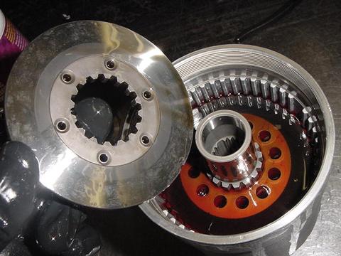
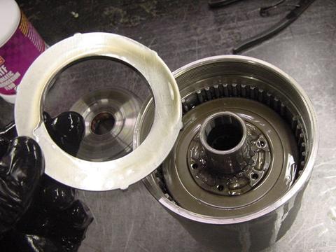
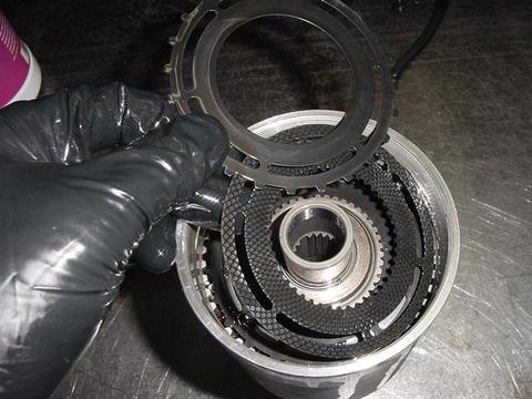
After checking, you can now go ahead and turn counterclockwise until it comes off. Pull the cap out:
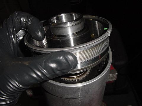
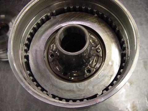
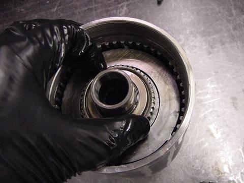
You can now take the unit off the vise, turn it upside down and drain all fluids and remove all parts. Please note there are 6 balls in there, don't lose them.
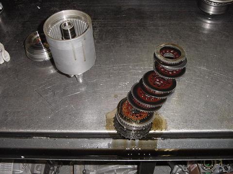
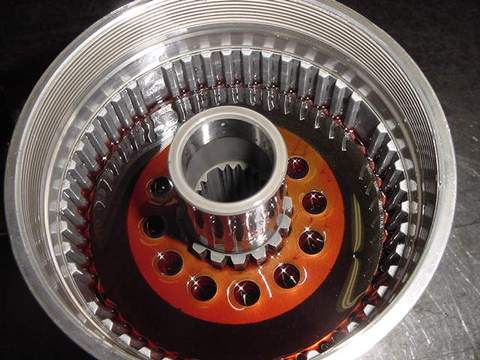
Helpful tip. To verify clutches are good, take all 9 frictions and steels and line then up together. Measure the total thickness. If it's 35-36mm, they are in great shape. Less than 35 and you have wear:
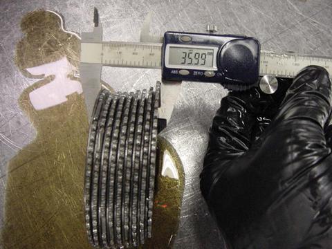
As you can see, this 2k mile trans has plates in great shape! We are just going to reuse these as replacing them seems like a waste of money at this point and are going to discount the total costs to the customer. The fluid also looked new, so we know these have not been under any load or stress through the life so far.
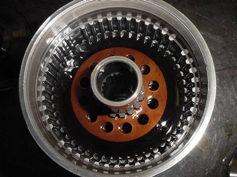
Install the clutches with a steel plate first, then friction. Go steel, friction, steel, friction 9 times until a friction is at the top.
Helpful tip, line all of the frictions so all of the holes are aligned all the way down. This allows for better heat and fluid movement to keep things cooler.
Now fill the unit with fluid. In this case, this car is getting our Drag 800 build, so we are filling it with our race RED fluid. Note, fill the unit up to the top friction. Do not fill any more as this is where it needs to be:
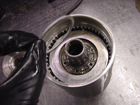
Install the upper thick plate which contains the balls as you see in the picture below. Note I am showing the end which faces DOWN.
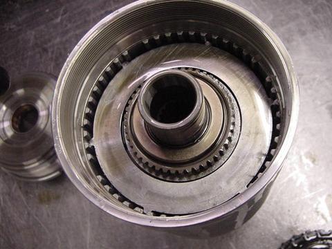
Next install the center plate:
It should look like this below:
Now would be a good time to install our ball retaining ring we sell HERE. This will prevent costly and catastrophic failure of the unit and keep the balls in position. This modification can save you thousands of dollars!
Next install the balls and upper ball plate:
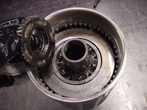
Install bearing as you see in the picture. Note, side you see in the first picture needs to face DOWN:
To assure the balls are in the correct position. Turn the upper ball cap by hand until it stops, then turn the other direction. Note, you must also be applying downward pressure as well as turning. When you go back to center, it should feel like it moves down and is at a low point.
Next install the metal steels and frictions. Same as before, plate first, friction, then plate and friction until you have the 5th piece which is the plate at the top.
Very carefully, without moving anything around, put the unit back on the vise and install the main cap. Tighten the cap until it stops and then loosen 45 degrees:

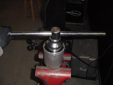
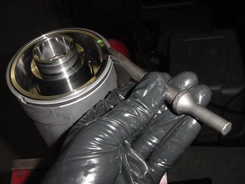
Take your shaft tool pictured below and see if you can turn the shaft by hand:

This should require a lot of effort, but you should be able to turn it. If you can, then the unit is preloading correctly and the balls are working. Again, it's supposed to be very difficult to turn and that's OK.
Now tighten the cap again until it stops and loosen 90 degrees.
Put a torque wrench on the shaft tool and measure the resistance. In applications which use the OEM weak output shaft, you want the resistance to be 20-25nm. If you have a billet shaft, tighten the cap slightly until you can turn the shaft with 25nm. 20nm is safe and will allow the front drive parts of your car to live, tighter and more parts in the drive-train can break. In order to hit the correct resistance/torque value, you will obviously need to tighten and loosen the cap to change preloading.
Tighten the retaining ring around the cap after your values are set.
Install the coil and c-clip.
You're done!
Disclaimer: Note that this unit pictured above was in great shape. It is your responsibility to purchase and replace parts as needed which are damaged. Inspection of every part is critical and we take no responsibility for any problems which you may have during this process. This page was created as a courtesy for our customers which want to service the unit themselves. If you want to be assured it's done right, have us rebuild the unit here in-house. More details of the Jacks Trans ETS rebuild process HERE.
Please feel free to EMAIL us.
